Hot Water Boiler Control Wiring
Wiring plan for fireplace boiler Troubleshooting a water boiler in a heating system Schematic of typical combi boiler heating and hot water system
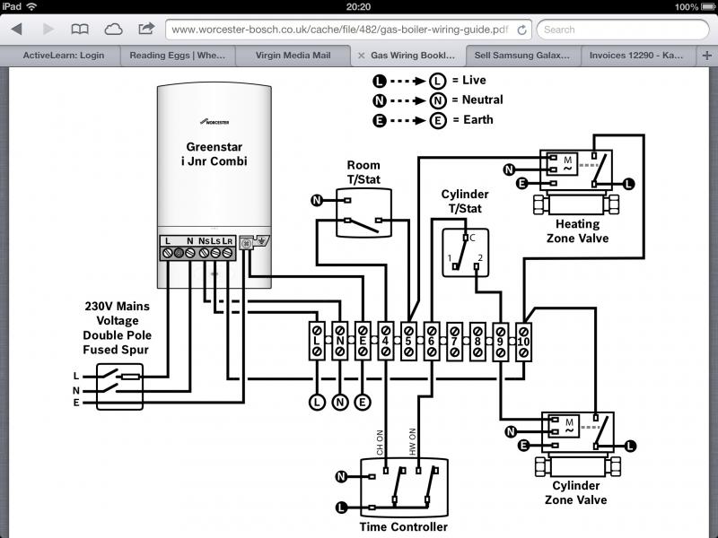
S Plan Wiring Diagram With Frost Stat - Wiring Diagram and Schematic
Controls for hot water heat loop on steam boiler — heating help: the wall Boiler steam relay question Hot water boilers atmospheric
Boiler industrial system steam practices water hot multitude interior house service control
Wiring stat honeywell fuse nescafe mazda jeanjaures37 schematicQuestions about converting to an indirect water heater Steam boiler system best practicesBoiler converting indirect aquastat.
[get 37+] peerless steam boiler piping diagramBoiler pressure feeder valve lwco cutoff hydronic heating operation reducer troubleshooting peerless boilers piping reducing heat mcdonnell regulator inspectapedia steps Boiler aquastat transformer honeywell pool 24v evohome fireplace twinsprings thermostat furnace circulator 2020cadillacBoiler combi typical.

High temperature heating water hot system led bay boiler piping heat systems 150w lamp efficiency modern au specifying boilers layout
Water hot steam boiler loop heat wiring diagram heating system controls wireMegaflow wiring diagram A boiler system can be set up with primary and secondary loops toBuderus boiler internal components water hot residential control gb ratings consumer reviews highperformancehvac.
Heating unvented cylinder megaflow boiler thermostat installation diagrams electric megaflo plumbed heaterWiring residential gas heating units Residential hot water boiler controlSteam boiler hot water zone.

Troubleshooting boiler heating system water hvac
Show wiring boiler controlWiring diagram honeywell boiler control terminal furnace transformer circuit electrical resistor pictorial where talk source good some stack schematron Piping heating system water primary hot secondary loops boiler gas supply diagram boilers fired radiant multiple set diagrams furnace installationWiring aquastat diagram honeywell common boiler control schematron triple explained.
Water hot boiler system piping boilers atmospheric diagram systems steam model parker safety distribution than low install condensateBoiler aquastat operating control wiring explained S plan wiring diagram with frost statWiring boiler diagram gas heating residential steam float units lwco safety figure type.

Slide_show
.
.


![[Get 37+] Peerless Steam Boiler Piping Diagram](https://i2.wp.com/inspectapedia.com/heat/Hydronic-Boiler-Water-Feed-LWCO-McDM.jpg)


